
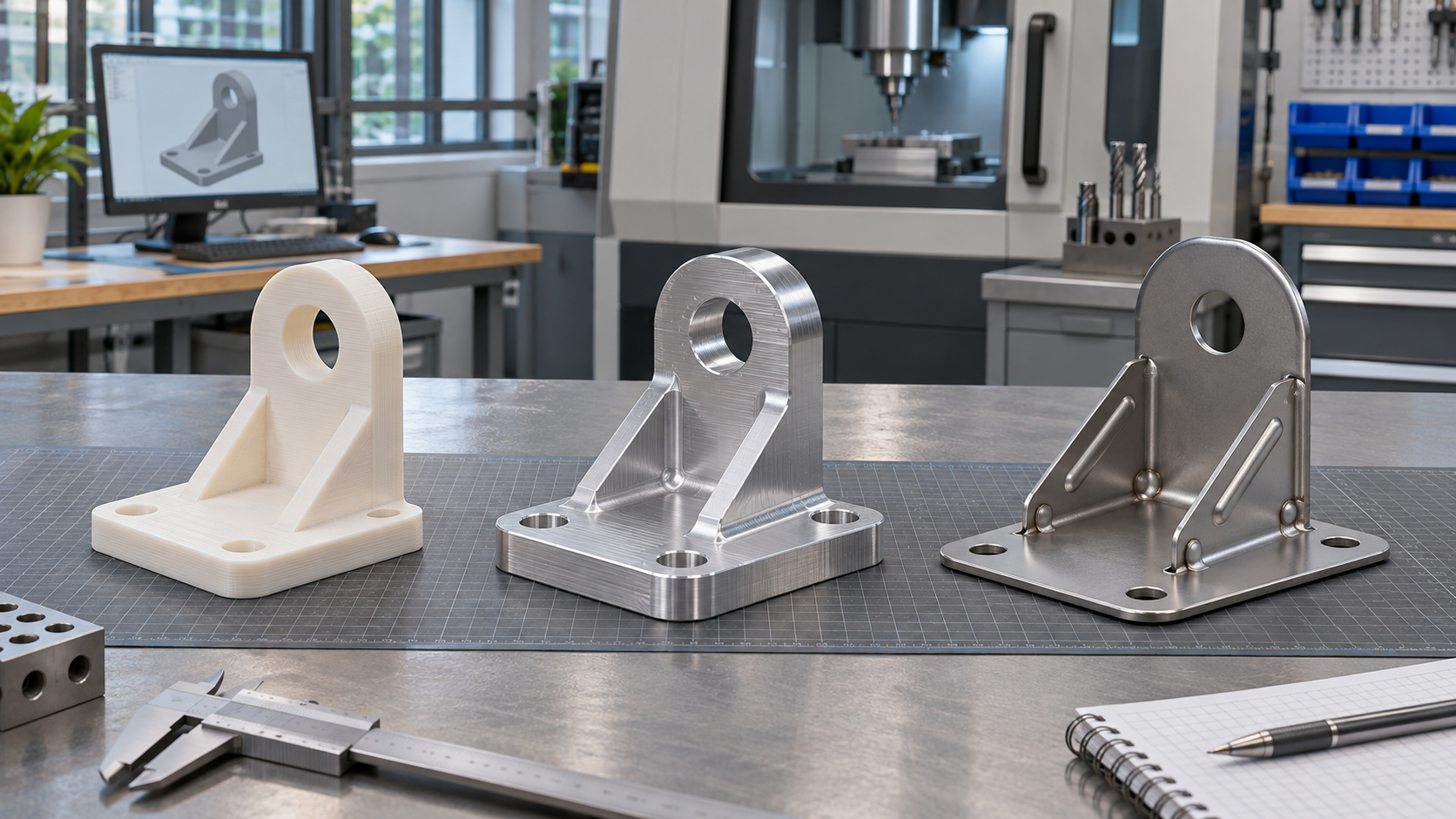
Teams often ask which manufacturing process is best for a prototype as if the answer should remain fixed from concept to production. It rarely does. The process that quickly exposes a packaging conflict may be a poor choice for a load test. The route that produces a convincing functional sample may still hide the effects of tooling, forming, joining, or batch variation that matter before production release.
Process selection is better treated as a sequence of engineering decisions. At each stage, the team screens out infeasible routes, ranks the remaining options against the current question, and records what the chosen build cannot prove. As requirements mature, the evidence changes—and the manufacturing route may need to change with it.
1. A prototype process is part of the experiment
A prototype is not only a shape delivered by a supplier. Its material state, manufacturing history, joints, orientation, supports, fixtures, and finishing steps can affect what engineers observe. A polymer additive model can be excellent for checking envelope, access, and assembly sequence. It should not automatically be treated as evidence for the stiffness, fatigue behavior, thermal response, or production variation of a later metal part.
The same distinction applies within a process family. A machined part made from wrought stock can preserve important geometry and material properties, but it will not reproduce every feature of a casting or formed sheet component. A metal additive part may enable internal channels or consolidated geometry, yet its build orientation, support strategy, post-processing, and inspection needs become part of the evidence boundary.
This is why the first question should not be “Which process is fastest?” It should be “What decision must this build enable?” Once the decision is explicit, process selection becomes a test-design problem instead of a popularity contest among CNC machining, 3D printing, sheet metal fabrication, molding, and hybrid routes.
2. Separate feasibility screening from preference ranking
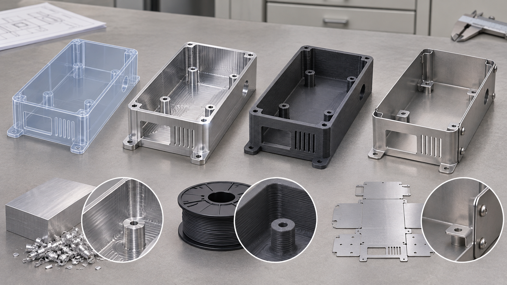
Screen out physically unsuitable routes before ranking feasible options by learning value, time, inspection, and transfer to production.
Decision tools can create a false sense of precision when every option receives a score even though some routes are physically unsuitable. Begin with hard constraints. Can the process handle the required material class, part envelope, minimum accessible features, enclosed geometry, wall behavior, quantity, and necessary post-processing? Can it produce the interfaces that must be measured or assembled? If not, remove it before discussing cost, speed, or familiarity.
Only then rank the feasible options. Useful criteria include how faithfully the route represents the test physics, how quickly it can support the next decision, what redesign it demands, what inspection is possible, and whether the resulting evidence transfers to the intended production route. Weighting may help make priorities visible, but a numeric total does not eliminate engineering judgment.
A systematic review of manufacturing decision tools found recurring limits such as narrow scope, inconsistent application, data-management gaps, and weak integration into real workflows. The practical lesson is not to abandon structured comparison. It is to preserve assumptions, uncertainty, and the reason an option was excluded. That record becomes valuable when the design or requirement changes.
3. The route should change when the learning objective changes
Prototype maturity is not just an increase in polish. Each stage should retire a different risk. An early build may answer whether the product fits its available space. A functional build may test motion, load path, sealing, heat transfer, or user interaction. A production-intent build may examine process-specific variation, assembly sequence, inspection strategy, and repeatability.
| Stage | Primary question | Process priority | Evidence to retain |
|---|---|---|---|
| Concept or form model | Is the envelope, access, or interface idea viable? | Fast geometry changes and clear physical review | Interference log, interface changes, decision notes |
| Engineering prototype | Does the mechanism or load path behave as expected? | Representative geometry, material properties, and boundary conditions | Test setup, measured response, failure mode, revision |
| Integration prototype | Do parts, people, controls, and assembly steps work together? | Interface accuracy and realistic joining or handling | Assembly sequence, access issues, fit records, observations |
| Production-intent sample | Can the intended route meet acceptance requirements consistently? | Production-relevant material, process history, and inspection | Dimensional results, defects, process conditions, traceability |
A published steering-knuckle development study illustrates the boundary clearly: a polymer additive prototype supported packaging, clearance, accessibility, and assembly checks, while metallic routes remained necessary for load-bearing evidence. The point is not that one process is superior. Each route is useful when its output matches the question.
4. Geometry, material, quantity, and acceptance move together
Process decisions fail when requirements are considered one at a time. A complex internal channel may favor additive manufacturing, but the chosen material, required internal condition, inspection access, and later quantity may alter that conclusion. A sheet-metal route may be attractive for a bracket, but bend access, flange length, springback, joining, and the need for forming tools influence both feasibility and the value of the prototype.
Quantity also changes the decision. A one-off machined sample may be a sensible way to test interfaces while geometry is fluid. It does not prove that the intended high-volume process will produce the same variation pattern. Conversely, building production-like tooling too early can lock in geometry before the critical interfaces have been learned.
Acceptance requirements should therefore enter the comparison at the beginning. If the decision depends on internal features, surface integrity, leak behavior, or free-state geometry after release from a fixture, the process and inspection plan must make that evidence observable. A route that can make the part but cannot support the needed measurement may still be a poor experimental choice.
5. Update the decision without discarding earlier work
Changing processes does not mean the earlier prototype was wasted. Preserve the decision trail: the question, requirements used, routes screened out, weighting or tradeoff logic, known surrogates, test results, and remaining uncertainty. When maturity increases, update only the inputs that changed.
For example, an early enclosure study may establish external packaging and connector locations using a printed model. The next decision may introduce production material, sealing surfaces, heat paths, and controlled datums. Those new requirements can eliminate or reorder routes without invalidating the packaging evidence already collected. The team should carry forward confirmed interfaces while reopening only the assumptions affected by material or process history.
Research integrating manufacturing-process selection with design emphasizes this iterative relationship. Process choice influences geometry and design detail, while design changes alter the feasible process set. Treating the record as a living decision model prevents repeated debates and makes supplier feedback easier to incorporate.
6. Build a comparable process-selection brief
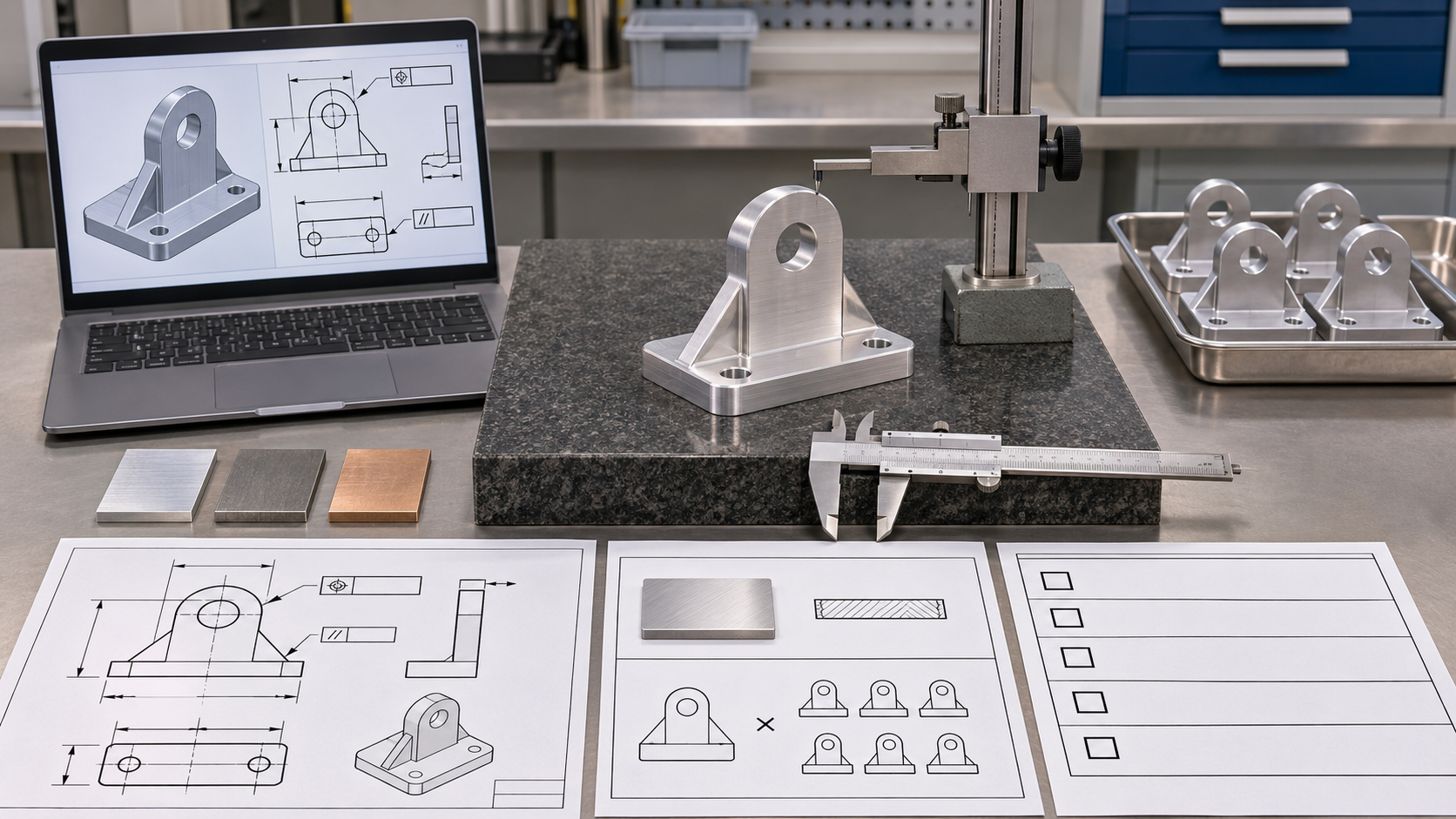
A comparable RFQ connects geometry, material, quantity, test conditions, and acceptance evidence to one explicit decision.
A supplier cannot compare routes reliably from a CAD file alone. Provide a compact brief that separates fixed requirements from negotiable preferences. Include:
- Decision: what engineering or buying action the prototype must support.
- Geometry: controlled model revision, critical interfaces, datums, and features that may be simplified.
- Material: exact grade when essential, or the property range when a surrogate is acceptable.
- Quantity and sequence: current build quantity, expected iterations, and possible later volume.
- Test conditions: loads, temperature, fluids, duty cycle, assembly constraints, or user interaction.
- Acceptance evidence: measurements, material records, surface or internal checks, and the state in which the part is inspected.
- Intended production route: known target process or the reasons it remains undecided.
This brief allows CNC machining, additive manufacturing, sheet metal, molding, or hybrid proposals to be compared against the same question. It also gives the manufacturer room to identify a feasibility constraint or propose a staged build rather than quoting an unsuitable route exactly as requested.
7. Use each build to improve the next process decision
Close every prototype cycle with three statements: what the build demonstrated, what it did not represent, and what decision follows. If the result is inconclusive, identify whether the problem came from the design, the manufacturing surrogate, the test method, or missing measurement. That distinction determines whether the next step is a geometry revision, a different material, a new process route, or a better-controlled experiment.
Process selection should become more evidence-based as the project matures, not merely more expensive. Early routes maximize learning per iteration. Later routes preserve the material, process history, interfaces, and variation that matter for release. A structured handoff between those stages is more reliable than expecting one prototype to answer every question.
Review the available manufacturing process paths as candidates rather than predetermined answers. When the decision brief is ready, use the project intake to share the controlled CAD model, critical drawing requirements, material or property target, quantity, intended test, planned production route, and required acceptance evidence. The next step is a route comparison tied to the current learning objective and its limits.