
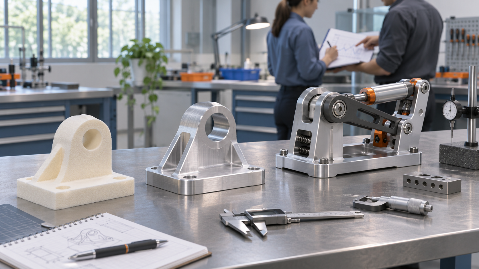
A prototype can look almost finished and still answer the wrong question. A polished model may be excellent for a stakeholder review but unsuitable for measuring thermal behavior. A machined metal part may reveal fit and load-path problems yet say little about an injection-molded snap feature. Conversely, a simple fixture, partial assembly, or surrogate-material model can be the fastest route to a defensible decision when its fidelity matches the uncertainty under test.
Prototype fidelity is therefore not a single ladder from rough to realistic. It is a set of choices about what the build must represent: geometry, material response, interfaces, appearance, manufacturing route, operating environment, and user interaction. The practical goal is to preserve the attributes that determine the next decision while simplifying the rest. That turns a prototype from an object to admire into an evidence-generating experiment.
1. Start with the decision, not the manufacturing process
Before choosing CNC machining, 3D printing, sheet metal fabrication, molding, or a hybrid route, write the decision the prototype must enable. Useful statements are specific: confirm that two components assemble without interference; compare two handle geometries with users; verify that a bracket survives a defined static load; determine whether a cooling path distributes flow; or release a design for tooling after critical dimensions are measured.
A decision statement exposes what must be represented and what can remain simplified. If the question is packaging, external geometry and interface locations may matter more than production material. If the question is stiffness, material properties, wall section, constraints, and load direction become central. If the question is molding behavior, a machined look-alike may not reproduce knit lines, shrinkage, fiber orientation, draft, or ejection effects. The process should follow the evidence requirement.
Research on prototyping as a decision instrument emphasizes uncertainty reduction rather than realism for its own sake. The right prototype targets the unknown that could change the design, test plan, supplier choice, or investment decision. Write that unknown explicitly, name who will use the result, and define what action follows a pass, a failure, or an inconclusive outcome.
2. Fidelity has several independent dimensions
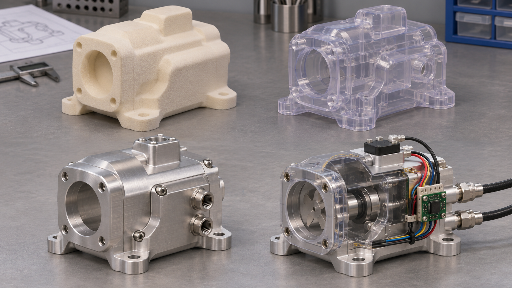
Teams often call a prototype low- or high-fidelity without saying what is faithful. That shorthand hides important tradeoffs. A build may be geometrically accurate but made from a surrogate polymer. It may use production material but omit the final finish. It may reproduce controls and user interaction while its internal mechanism is simulated. Treat fidelity as a profile across several dimensions:
- Geometric fidelity: overall envelope, interfaces, datums, wall sections, clearances, and critical features.
- Material fidelity: stiffness, strength, friction, thermal behavior, chemical resistance, transparency, or electrical properties.
- Functional fidelity: forces, motion, flow, heat transfer, sealing, sensing, control logic, or load paths.
- Manufacturing fidelity: the extent to which tooling, process history, orientation, joints, residual stress, surface condition, and variation resemble the intended route.
- Interaction fidelity: what a user, operator, installer, or maintainer sees, touches, hears, and does.
- Environmental fidelity: temperature, humidity, vibration, contamination, pressure, duty cycle, and boundary conditions.
A generalized 2026 engineering framework describes fidelity progression as an adaptive choice shaped by risk, stakeholders, uncertainty, and validation results. This matters because the dimensions do not need to rise together. A transparent polymer housing can provide high interaction and packaging fidelity with low material fidelity. A coupon can provide high material and process fidelity with almost no product geometry. A modular rig can reproduce a control interface and load response before the full enclosure exists.
3. Use the smallest prototype that preserves the test physics
Simplification is useful only when it does not remove the mechanism being evaluated. For a static fit check, a nonfunctional shell may be enough. For a snap joint, the local geometry, material, print orientation or molding history, and repeated insertion cycle may all affect the result. For a heat-transfer question, surface finish may be irrelevant while contact pressure, interface material, flow path, and boundary temperature are decisive.
Ask four questions for every proposed simplification. First, does it change the load path or boundary condition? Second, does it remove a failure mode the test is supposed to expose? Third, does it alter the measurement enough to change the decision? Fourth, can the difference be modeled or bounded with an explicit correction? If the answer is uncertain, use a focused coupon, subassembly, or comparative test before paying for a full build.
Hybrid physical-digital prototypes can be especially valuable. Research combining simulation, physical rigs, and humans in the loop shows that operational or interaction flaws may emerge even when conventional analysis appears acceptable. Other work on modular smart hybrid prototyping demonstrates how real hardware can preserve physical interaction while unavailable product elements are represented by synchronized digital models. These approaches are not substitutes for final verification; they are ways to obtain the right learning earlier.
4. Match the build to the question with a fidelity matrix
| Question | Fidelity that usually matters | Possible prototype | Evidence to collect |
|---|---|---|---|
| Will it fit and assemble? | Envelope, datums, interfaces, clearances, access | Printed or machined components, partial assembly | Interference record, measured gaps, assembly sequence, issue log |
| Will it carry the load? | Material state, section geometry, joints, constraints | Coupon plus representative subassembly | Load-displacement curve, strain or deflection, failure location |
| Will users operate it correctly? | Controls, reach, feedback, sequence, resistance | Appearance shell with functional controls or hybrid rig | Task completion, observed errors, forces, structured feedback |
| Will the thermal or flow concept work? | Path geometry, interfaces, boundary conditions, sensors | Instrumented flow or thermal rig | Temperature, pressure drop, flow distribution, repeatability |
| Is the design ready for production tooling? | Production material and process, critical dimensions, variation | Production-intent trial or representative tool insert | Dimensional study, defects, process window, inspection plan |
The matrix should be project-specific. It is not a promise that one prototype route can prove every condition. It is a negotiation tool: engineering, testing, procurement, and the manufacturer can see which attributes are controlled, which are surrogate, and which remain outside the test. This reduces the common failure in which stakeholders silently expect a single build to prove appearance, function, durability, and production readiness at once.
5. Define the evidence before requesting the part
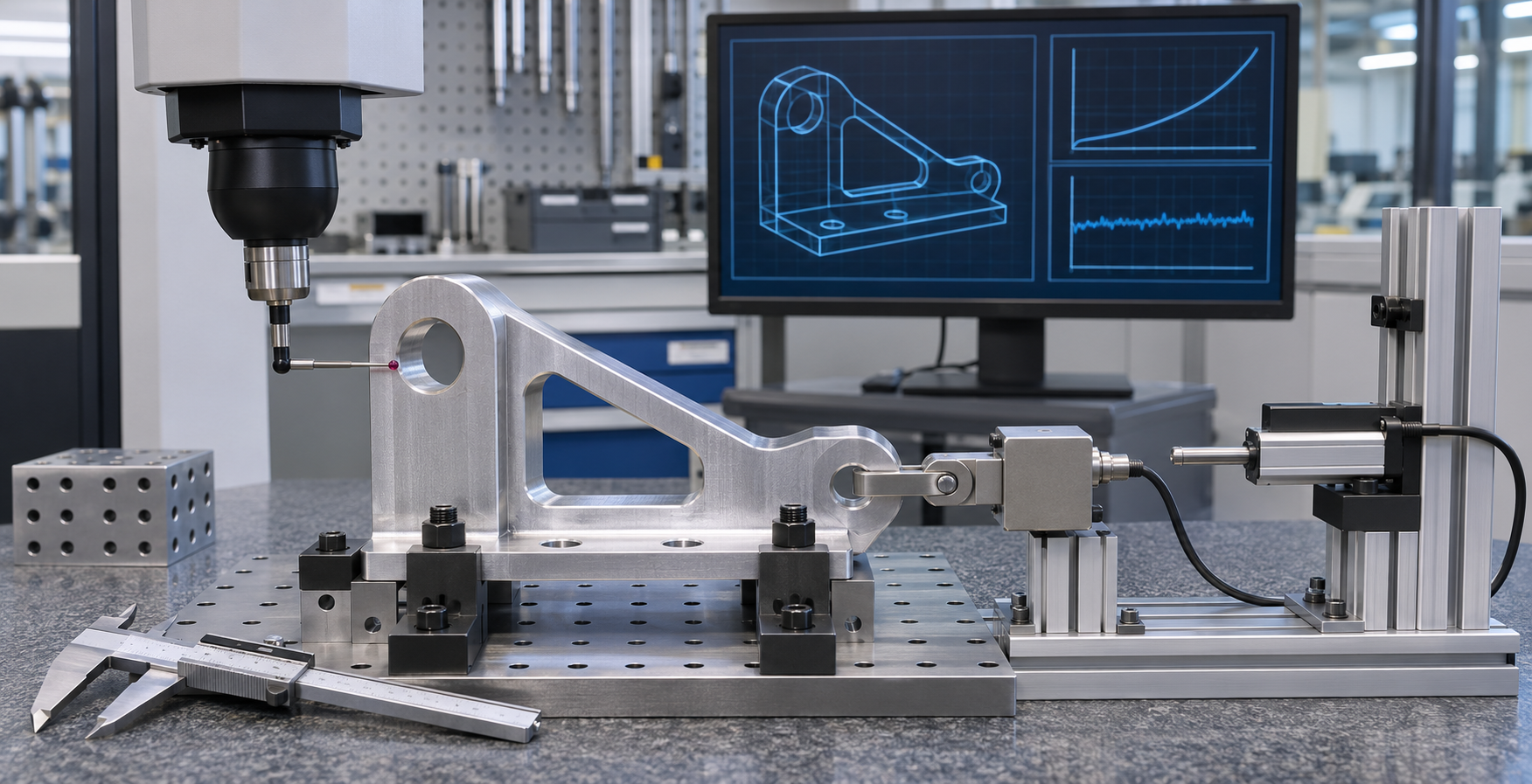
A prototype without a measurement plan often produces opinions instead of learning. Define the response variables, instruments, fixtures, sample count, operating sequence, environmental condition, and acceptance logic before manufacturing. Record the revision of the CAD model and drawing, material and condition, process route, orientation or setup where relevant, post-processing, and any deviation from the intended product.
Acceptance should reflect the decision. A form model may need a documented fit review rather than a full dimensional report. A functional bracket may need controlled datums, fixture definition, load-displacement data, and photographs of failure. An interaction model may need a task script and observation rubric. A production-intent trial may need evidence on dimensional variation, surface or internal defects, and the process conditions under which the results were obtained.
The evidence plan also protects against false confidence. If a result depends on a surrogate material, scaled geometry, ideal boundary condition, or one-off build, state that limitation beside the result. The next prototype should close the most decision-critical gap, not merely add detail. The site's quality planning overview can help frame which inspection records belong with a particular build.
6. Scope an RFQ around learning, not just part count
A useful prototype RFQ includes more than CAD, material, quantity, and date. Explain the decision to be made, the uncertainty being tested, the intended process after prototyping, the critical interfaces, and the evidence required. Identify which attributes must be representative and which may be simplified. If several builds form a sequence, state what each stage should teach before the next stage begins.
For example, a sensible progression might use a low-cost form model for packaging, a representative subassembly for load and interface tests, and a production-intent sample only after geometry and requirements stabilize. Front-loading digital analysis, design-for-manufacture review, and focused experiments can reduce avoidable physical loops, but each digital result still needs assumptions, verification boundaries, and a path to physical confirmation.
Review the available manufacturing processes and material options as inputs to this plan, not as the starting answer. Then use the project quote form to provide the CAD model, controlled drawing, quantity, intended test, critical interfaces, target material or property, and required inspection evidence. The next step is to compare a practical prototype route with the fidelity and evidence your decision actually requires.